
Leave a Message
We will call you back soon!
Your message must be between 20-3,000 characters!
Please check your E-mail!
More information facilitates better communication.
Submitted successfully!
We will call you back soon!
Leave a Message
We will call you back soon!
Your message must be between 20-3,000 characters!
Please check your E-mail!
| Place of Origin: | CHINA |
|---|---|
| Brand Name: | OASIS |
| Certification: | GB/T 19001-2016/ISO9001:2015 |
| Model Number: | OASIS-2024-11-02 |
| Minimum Order Quantity: | 10 Meter/Meters |
| Price: | Negotiation |
| Packaging Details: | Wooden cases or pallet or bundle or container or according to clients' requirements |
| Delivery Time: | Within 35 days |
| Payment Terms: | L/C, T/T |
| Supply Ability: | 6000 Meter/Meters per Month |
| Material: | Stainless Steel | Filter Rate: | Up To 65% |
|---|---|---|---|
| Slot Size: | 0.02 -- 6.00mm | Operating Temperature: | Up To 200°C |
| Color: | Metal Color | Productname: | Pipe Base Screen |
| Application: | Filtration And Separation | Type: | Filter Cylinder |
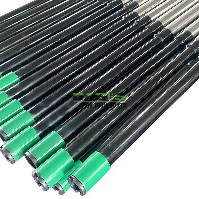
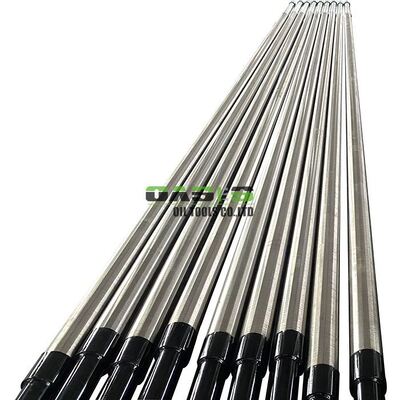
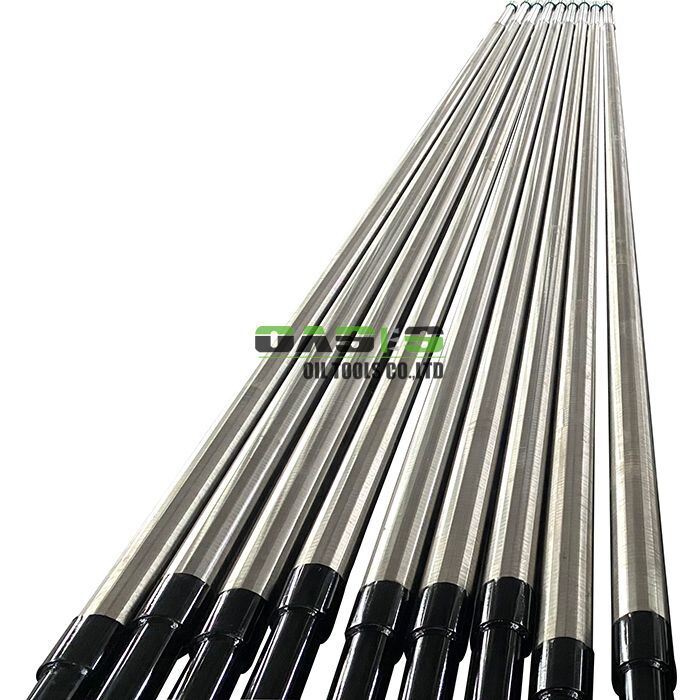
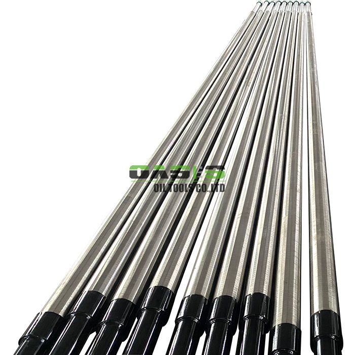
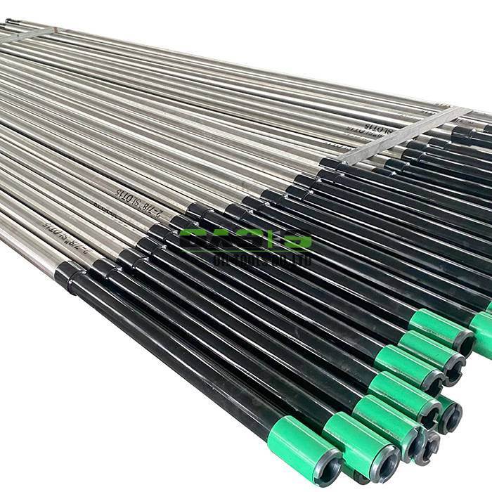
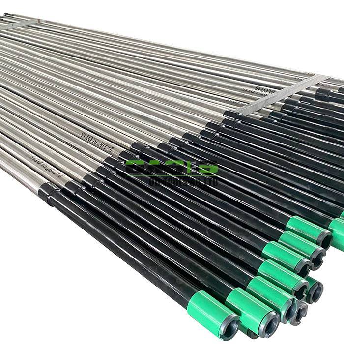
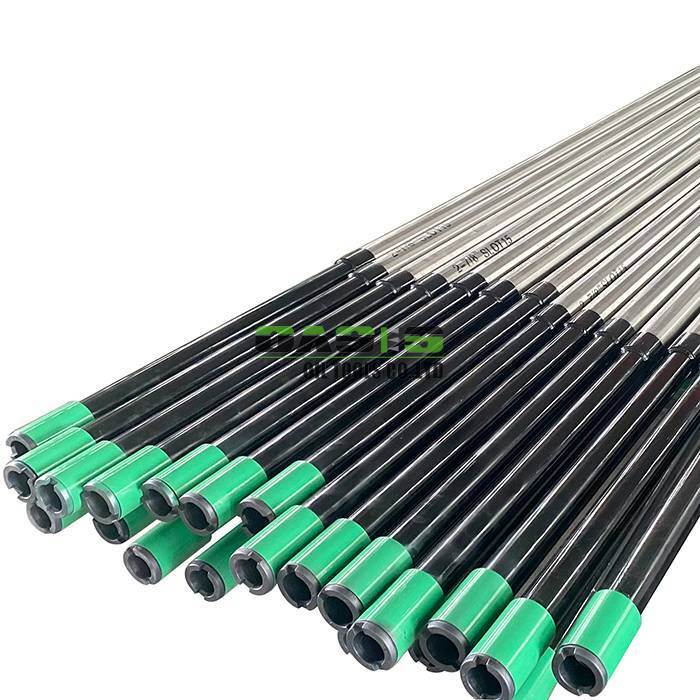
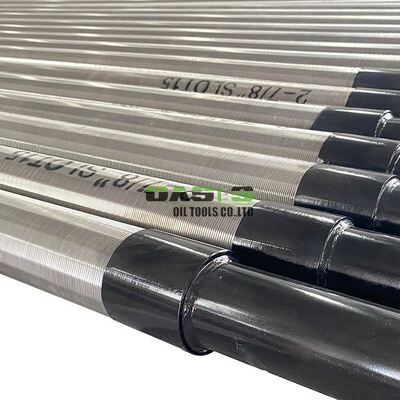
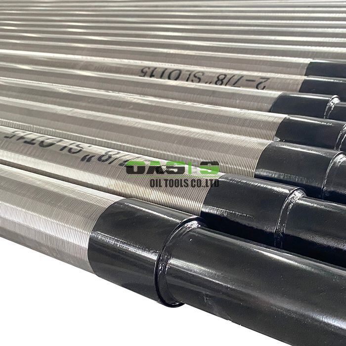
The Rod Base Screen is a premium sand control solution that combines a precision-perforated base pipe with a continuous-slot wire-wound jacket, built over a rugged array of longitudinal support rods. This three-element construction – base pipe, support rods, and outer wire jacket – delivers superior mechanical strength and accurate filtration in a single, runnable assembly.
For this specific offering, we present a 2-7/8″ (73.0 mm) unit with a Slot 15 (0.015″ / 0.38 mm) gap – a configuration ideally suited for slimhole completions, workover interventions, and wells producing from fine-to-medium grained formations. Whether you're operating a vertical producer, a deviated well, or a deep water supply bore, the Rod Base Screen gives you reliable sand retention without sacrificing production rates.
Built with material options ranging from carbon steel grades (J55, K55, N80, L80, P110) for the base pipe to stainless steels (304, 304L, 316L) for the support rods and outer jacket, the system adapts to your downhole fluid chemistry – from sweet service to mildly sour environments. The Rod Base Screen is engineered for operators who demand structural integrity, filtration precision, and long-term reliability in a single package.
![]()
Triple-element construction – inner perforated base pipe provides burst and collapse resistance; longitudinal support rods add axial strength and maintain annular spacing; outer wedge-wire jacket delivers precise slot control. Together, they outperform conventional screens in structural integrity and filtration accuracy.
Self-cleaning slot geometry – the V-shaped wire profile creates diverging slots that prevent particle bridging, allowing fines to pass while keeping formation sand outside the screen. This significantly reduces plugging and extends run life.
All-welded assembly – the wire is fusion-welded to every support rod intersection, and the rods are welded to the base pipe at each end, ensuring the Rod Base Screen maintains its roundness and gap consistency even under compaction, thermal cycling, or bending during horizontal deployment.
Full thread compatibility – available with EUE, NUE, BTC, STC, or LTC connections, so you can stab it directly into your existing tubing or casing string without custom adaptors.
Wide material selection – base pipe grades from J55 to P110; support rods and jacket materials from 304L to Duplex 2507, giving you the freedom to match metallurgy to your specific well fluids (chlorides, H₂S, CO₂, pH).
Length flexibility – sections from 0 to 12 meters, allowing you to build blank-screen-blank configurations exactly as your completion design requires.
Enhanced collapse resistance – the support rod system adds an extra layer of structural reinforcement, making the Rod Base Screen particularly suitable for deep wells and high-overburden environments.
The Rod Base Screen operates on a proven mechanical filtration principle with structural reinforcement at every level.
Step 1 – Outer jacket does the filtering
The continuous-slot wire-wound jacket, welded onto the support rods, acts as the primary filter medium. Formation fluids flow through the V-shaped slots, which are precisely gapped (in this case, 0.38 mm / Slot 15). The wedge wire profile creates a gradually widening passage from the outside in – this means that any particle small enough to enter the slot continues through without getting stuck, while larger grains are retained outside. This self-cleaning action minimizes plugging over time.
Step 2 – Support rods provide structural backbone
Running longitudinally between the base pipe and the outer jacket, the support rods serve multiple functions:
They maintain a consistent annular gap between the base pipe and the jacket, ensuring even flow distribution.
They add significant collapse resistance – the rods bear the brunt of external formation pressure, protecting the jacket from deformation.
They provide a robust weld base for the wire, ensuring every slot stays fixed and accurate throughout the screen's service life.
Step 3 – Perforated base pipe delivers flow and mechanical strength
Once the fluid passes through the jacket and flows between the support rods, it enters the base pipe through strategically staggered perforations (standard hole sizes: 9 mm, 11 mm, 16 mm, or 19 mm). The base pipe – being a heavy-walled tube – carries the primary mechanical loads: burst pressure from the inside, collapse pressure from the outside (shared with the rods), and axial tension/compression during running and production.
The result – a three-layer defense where:
The jacket provides accurate sand retention.
The support rods add collapse strength and maintain flow geometry.
The base pipe delivers primary pressure integrity and a secondary barrier against sand influx.
This layered approach means that even if the outer jacket experiences localized wear or damage, the support rods keep the assembly intact, and the base pipe's perforations (larger than the jacket slots) continue to allow flow while still providing a degree of solids retention.
Here are the detailed parameters for this specific Rod Base Screen configuration:
| Parameter | Specification |
|---|---|
| Product Type | Rod Base Screen (Perforated Base Pipe + Support Rods + Wire-Wound Jacket) |
| Base Pipe Outer Diameter | 2-7/8″ (73.0 mm) |
| Number of Support Rods | Standard: 6–12 rods depending on OD (customizable) |
| Screen Jacket OD | Nominal build-up ~3-1/8″ to 3-1/4″ depending on rod/wire thickness |
| Slot / Gap Size | Slot 15 (0.015 inches / 0.38 mm) – suitable for fine-to-medium sands |
| Base Pipe Material Options | J55, K55, N80, L80, P110, or 304 / 304L / 316L stainless |
| Support Rod Material | Same as jacket material (for galvanic compatibility) or as specified |
| Outer Jacket Material | 304L (standard) / 316L / Duplex 2205 / 2507 (upon request) |
| Base Pipe Perforation Size | Standard: 9 mm, 11 mm, 16 mm, or 19 mm diameter holes |
| Perforation Pattern | Staggered spiral arrangement for uniform flow distribution |
| End Connection Type | EUE, NUE, BTC, STC, or LTC – fully compatible with 2-7/8″ tubing |
| Overall Length | Customizable: 0 – 12 meters per section |
| Slot Tolerance | ±0.02 mm (verified by go/no-go gauges on every unit) |
Superior sand control – the 0.38 mm (Slot 15) gap is precision-calibrated to retain fine formation sands (d50 ~0.45–0.55 mm), significantly reducing solids production that can damage pumps, chokes, and surface equipment.
Extended run life – the self-cleaning V-wire design resists plugging far better than punched or slotted pipes, meaning fewer acid washes, fewer workovers, and lower OPEX over the life of the well.
High flow efficiency – the wedge-wire jacket offers an open area of 40–60%, and the support rods maintain a consistent annulus, which translates to lower pressure drops across the screen. You get more production per unit of drawdown – a critical advantage in low-pressure reservoirs.
Erosion resistance – by directing the flow through the jacket and over the rods first, the base pipe is shielded from abrasive sand impingement, preserving the integrity of the threaded connections and the production string.
Flexible material pairing – choose carbon steel for the base (cost-effective) and stainless for the rods and jacket (corrosion-resistant), or go all-stainless for sour service. You pay only for the protection you actually need.
Q1: What does "Slot 15" mean in practice?
Slot 15 refers to a gap width of 0.015 inches, which equals approximately 0.38 millimeters. This is a standard industry designation used for wire-wound screens. For formation sand with a median grain size (d50) around 0.45–0.55 mm, Slot 15 typically retains about 80–90% of the solids while allowing clear fluids to pass.
Q2: How does the Rod Base Screen differ from a standard dual-layer screen?
A standard dual-layer screen combines a perforated base pipe with an outer wire jacket, with the jacket welded directly to the base pipe at the ends. The Rod Base Screen adds longitudinal support rods between the base pipe and the jacket, which are welded to both. This gives the Rod Base Screen significantly higher collapse resistance, better annular flow distribution, and a more robust connection between the jacket and the base pipe – making it the preferred choice for deep wells and high-pressure completions.
Q3: How do I choose the right slot size for my well?
The ideal slot size is determined by a formation sand sieve analysis. We recommend sending us a representative sand sample – our engineering team will run the analysis and recommend the optimal gap (typically Slot 8, 10, 12, 15, 20, 30 depending on your d10, d40, and d90 values). For Slot 15, we typically recommend it for fine-to-medium sands.
Q4: Can the Rod Base Screen be used in horizontal wells?
Absolutely. The all-welded construction – with wire welded to every support rod – gives the screen excellent collapse resistance and maintains roundness even when run through build sections and tight radius bends. The support rods also add stiffness, reducing the risk of buckling during deployment. The 2-7/8″ OD is also slim enough to navigate most horizontal casing programs.
Q5: What's the maximum length per section?
We manufacture sections up to 12 meters (approximately 39 feet) per joint. For longer intervals, multiple sections can be connected using threaded couplings or welded joints, with blank pipe sections in between as your completion design requires.
Ready to order or need a recommendation?
Contact OASIS technical sales team with your well data (formation sand size, fluid chemistry, depth, and completion type). We'll confirm whether this 2-7/8″ / Slot 15 Rod Base Screen is your optimal solution – or tailor a new spec just for you.
![]()
![]()